New user's registration have been closed due to high spamming and low trafic on this forum. Please contact forum admins directly if you need an account. Thanks !

Serial console access

Discuss development on Bubba
Post Reply
fredrikj
Posts: 45
Joined: 27 Jul 2011, 12:31

Serial console access

Post by fredrikj »

Today I once again found myself wanting serial console access to my b3. While the rescue boot usb image works fine, I imagine that it is a bit more convenient to just connect to the console via usb.

Anyone know if the follwing converter could work, as an alternative to the one mentioned on the wiki¹?

https://www.electrokit.com/en/product/u ... -cp2102-2/
https://www.electrokit.com/uploads/prod ... cp2102.pdf

¹ http://wiki.excito.com/w/index.php/Seri ... cess_on_B3

På förekommen anledning som det heter... :)
Last edited by fredrikj on 19 Jul 2019, 10:11, edited 1 time in total.
fredrikj
Posts: 45
Joined: 27 Jul 2011, 12:31

Re: Serial console access via a Rasberry Pi?

Post by fredrikj »

What about connecting the serial console via a Raspberry Pi? Are they pin compatible? Can I just connect pin cables directly between GPIO14+15 on the rpi and the rx/tx solering points on the b3?

https://www.raspberrypi.org/documentation/usage/gpio/
https://elinux.org/RPi_Serial_Connection

The elinux wiki page mentions that "it's probably a good idea to connect the signals with a 2.2 kΩ resistors in series". Is that relevant only to the tx/rx lines, or should one do that for the ground cable too?
Gordon
Posts: 1461
Joined: 10 Aug 2011, 03:18

Re: Serial console access

Post by Gordon »

Pretty sure that the FTDI galvanically separates input and output. This makes pretty good sense and I'm assuming the CP2102 does the same. In fact if I remember correctly Excito themselves had some type of electronic buffering between the 9-pin RS232 plug and the front header on the B3 board (Johannes posted an image of it on this board as he was cleaning out his garage). I would not create an electrical connection to a Pi.

Do note that the B3 board actually has 3 different locations where you can create a serial connection. There are the measuring points indicated in the wiki which I don't think is really what you should use to solder wires to. Next to the onboard battery there are two more convenient spots:
1: the print header which requires a special connector (I wouldn't solder here as well)
2: a row of holes that are meant for a 6-pin male header which is a real straight forward solder job.
fredrikj
Posts: 45
Joined: 27 Jul 2011, 12:31

Re: Serial console access

Post by fredrikj »

Gordon wrote: 18 Jul 2019, 04:58 Do note that the B3 board actually has 3 different locations where you can create a serial connection. Next to the onboard battery there are ... 2: a row of holes that are meant for a 6-pin male header which is a real straight forward solder job.
Oh, do you mean these? You wouldn't happen to know the pinout for those six holes? Which one is GND, TX, and RX for the serial port?

b3-6-pin-uart.jpg
b3-6-pin-uart.jpg (151.56 KiB) Viewed 14240 times
Gordon
Posts: 1461
Joined: 10 Aug 2011, 03:18

Re: Serial console access

Post by Gordon »

That's the one ;)

Shamefully, no. I did in fact not register which pins represented what. There might be some old forum post where I do mention them though. As I happen to have multiple units I opted for the special connector which makes it plug-and-play for every board. But you can simply "beep" the right pins with a multi-meter yourself, that's how I discovered them after finding out what the print header was for.
fredrikj
Posts: 45
Joined: 27 Jul 2011, 12:31

Re: Serial console access

Post by fredrikj »

Re the 6 hole pinout: I've determined¹ that pin 1 is GND but I was unable to detect TX/RX on any of the remaining five pins. I also took a macro photo on the bottom side of the PCB and tried to visually follow the traces from the TX/RX on the edge connector to the 6 holes. Again AFACT, while the traces for both TX and RX passes very close by and even straight between two holes, they never appear connect to any of the soldering holes. At least not on my board - could it vary on different board revisions perhaps?

I ended up soldering wires for RX and TX directly from the two surface testpoints, as is documented on the wiki. Ground is connected to pin hole 1.

Re connecting the serial port to a Raspberry Pi: It worked partially after a lot of tinkering. Best result was when I had 1 kohm resistors between the endpoints of each of the three wires respectively, ie TX/RX and GND and connected the micro-usb power connector for the Rasberry Pi to one of the USB ports on the B3. It didn't work at all when I powered the rpi from separate usb chargers.

Most attempts began with completely garbled output, see example below, but sometimes the signal appeared to stabilize after a while, after which a login prompt appeared as expected and I could log in. I even managed to reboot and follow the entire shutdown and bootup sequence from the console in one of my attempts.

Code: Select all

pi@raspberry:~ $ cu -s 115200 -l /dev/ttyAMA0
Connected.
�#��P�ōōō��P���RZ�Ƞ�_Z������R���ڶ�ZZZZ���ZZ���R�����ZZ�ZZRꈠ
Debian GNU/Linux 7 bubba ttyS0

bubba login: fredrik
Password:
I'm no electronics geek but it seems likely to me that this garbled data is caused by a bad signal. Possibly due to the absence of galvanic insulation between the Pi and the B3 - as you mentioned, Gordon. Anyone know if I can improve the signal isolation using two opto couplers, one for each RX and TX? F.x: https://www.electrokit.com/en/product/e ... o-coupler/

Well, anyway, I've satisfied most of my curiosity. My next step will be to buy the CP2102 usb-serial converter and see if I can get a better result with that.

¹ My multimeter doesn't have beep mode, so I selected 2 kohm resistance instead, on the assumption that infinite resistance implies no electrical connection. 🤷
Gordon
Posts: 1461
Joined: 10 Aug 2011, 03:18

Re: Serial console access

Post by Gordon »

Well, I just checked with a spare unit and I found Rx at 3 and Tx at 4. Don't know why that didn't work out for you.
fredrikj
Posts: 45
Joined: 27 Jul 2011, 12:31

Re: Serial console access

Post by fredrikj »

Gordon wrote: 19 Jul 2019, 12:11 Well, I just checked and I found Rx at 3 and Tx at 4. Don't know why that didn't work out for you.
Huh, that's interesting. It appears that the pinouts really do vary between board revisions! I have two B3:s, neither have TX/RX on 3 and 4.

Here's a photo of the bottom side of a B3 board, rev PC1, 2010. It has ground on pin 1, but the traces for TX and RX unfortunately zips by all the pin holes without connecting. The TX trace enters the image from the right and passes by just above the pin holes. The RX trace enters at the bottom of the image and passes by between the holes for pin 3 and 4.

Makes me wonder who laid out and inspected those traces and if they considered connecting them to any of the pinholes? Not enough coffee that day, or too much? They're so darn close, with the RX trace even precisely passing between two pins that appears to be otherwise unused. Oh, well. :)

b3-rev-pc1-2010-back-pinout.jpg
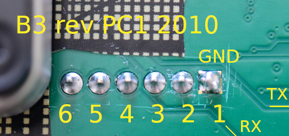
b3-rev-pc1-2010-back-pinout.jpg (161.96 KiB) Viewed 14212 times

Now, compare that to a photo of the bottom side of a B3 board, revision RF1, 2011. Again, ground attached to pin 1. However, unlike the rev PC1/2010 board, on the RF1/2011 board both TX and RX are connected to pins. TX is connected to 5 and RX is connected to 4.

b3-rev-re1-2011-back-pinout.jpg
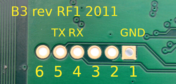
b3-rev-re1-2011-back-pinout.jpg (160.37 KiB) Viewed 14212 times

Curiously neither boards matches your pinout, Gordon. So what revision is your board?

I can imagine that this explains why the wiki page suggests surface soldering on the test points 65 and 66 on the top side of the board. TX and RX are simply not consistently connected to the pin holes between board revisions.

Personally, I prefer to solder a row of 6 male header pins (stiftlist) in the holes, rather than surface solder straight on to the test points, so that's what I'll do for my RF1/2011 board when I get around to it.
Gordon
Posts: 1461
Joined: 10 Aug 2011, 03:18

Re: Serial console access

Post by Gordon »

Just verified and the board on the spare unit is in fact an RF1 2011. Did not re-run the beep test. I guess I may have suffered from an occupational hazard, starting the count from 0 instead of 1.
Post Reply